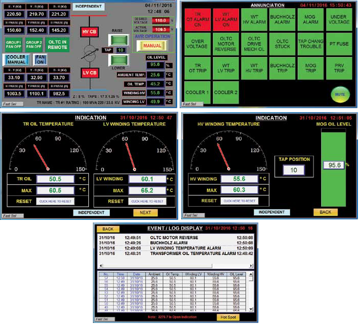
Image Not Found!
DATMEL TECHNOLOGY SDN BHD
" Towards Industry 4.0 and 100% Green Technology"
Image Not Found!
PRECIMEASURE Transformer Monitoring System (TMS)
Control and supervision of the transformer parameters from the TMS system through its HMI or from the substation computer.
Transformers are key components in any electric supply system. The breakdown of a transformer not only brings a lot of economical disadvantage for the energy supplier, but can also result in extreme losses for the consumer. For this reason, we have developed a processor controlled platform that can provide a comprehensive monitoring of the transformer. Control and supervision of the transformer is possible from the TMS system through its HMI or from the substation computer. All real time transformer parameters such as voltages, currents, oil / winding temperatures, oil level, tap position, alarms, trips etc are available in the system. Separate annunciation panels are no more required. In addition several diagnostic features can be in built into the systems that are helpful in the transformer asset management. These can cover transformer loss of life, tap statistics, real time over load capabilities etc. The system is capable of interfacing with several third parties individual IEDs such as Dissolved Gas analyzers, Bushing monitors, Fiber optic hot spot measurement systems, Smart breathers etc.
Image Not Found!
Powerful Micro-Processor Based System
The embedded Digital Tap Change control system enables monitoring of the tap changer and helps in voltage regulation of tap-changing transformers.
The powerful micro processor based system is architectured with the remote field mounted I/O system and a control room located panel. This localizes the hard wiring resulting in considerable cost savings and ease of maintenance. Data from the system is displayed in a user friendly manner for effective utilization by operating staff. The features that are provided for a given system shall be based on the customer needs as agreed during the project contract stage. Transformer Protective relays, synchronization equipment etc are generally not included in the scope of our TMS systems. Control and supervision of the cooling systems and tap changers can be provided from the TMS system as required. As described in the following the tap controls can be provided where parallel operation of transformers is envisaged through AVRs. Alarms caused due to any protective devices such as Buchholz, PRVs, temperature indicators, tap change gears, oil level indicators etc can be visualized through the TMS system, in addition to automatic time stamping and logging of such events.
Embedded Cooler Controls in TMS
Depending on the customer needs, it is possible for us to incorporate the cooler controls in the TMS itself, thus obviating the need for a separate cooler control unit. The fan and or pump controls based on the oil/winding temperatures, annunciations for any mal operation, periodic exercising of the cooling systems etc can be provided. The system monitoring and control from the substation control room or the remote SCADA control is possible through the communication interface. The standard communication is via MODBUS Ethernet. However, communication through IEC 61850 also can be supplied as required. In addition the communication cable can be of fiber optic type if desired. The human interface is provided through user friendly screens for control & supervision. The data from the system can be displayed in report or graphical manner for ease of analysis.
Image Not Found!
Parallel Operation of Similar Transformers
It is common in many stations to operate the transformers in parallel for meeting the load. In such cases it is necessary to ensure that the transformers have the same terminal voltage to prevent circulating currents since these can have a high magnitude and cause overheating. This can be overcome with the Master- Follower facility and special features that are built into the AVR system for this purpose. In case of parallel operation, it is necessary to know the transformers that are actually in parallel at any given time. Information for this is provided through the logic system. Each transformer is provided with a Master-Follower-Independent-Off selection facility.
AVR Settings
Parameters Values
Desired Voltage 100 - 120V
Bandwidth 0.5 to 9 %
Delay Time T1 1 to 999 Seconds
Delay Time T2 1 to 999 Seconds
Switching Pulse Duration 1 to 10 Seconds
Under Voltage Blocking 60 to 100% of desired voltage level
Over Voltage Blocking 100 to 140% of desired voltage level
PT Fuse Failure Blocking 0 to 50% of desired voltage level
Over Current Blocking 50 to 200% of current level
OLTC Parameter Monitoring Upper Limit, Lower Limit, Tap Change in Progress, Tap Changer Trouble, OLTC Stuck, OLTC Motor Reverse, OLTC Local/Remote, OLTC Drive Mechanism Overload, PT Fuse Fail etc.
Functional Scope
Scopes Descriptions
Temperature OTI, WTI, Ambient, HOT Spot etc.
Alarm / Trip Status Protective Device Buchholz, PRV, MOG, Temperature Indicators, OLTC Parameters etc.
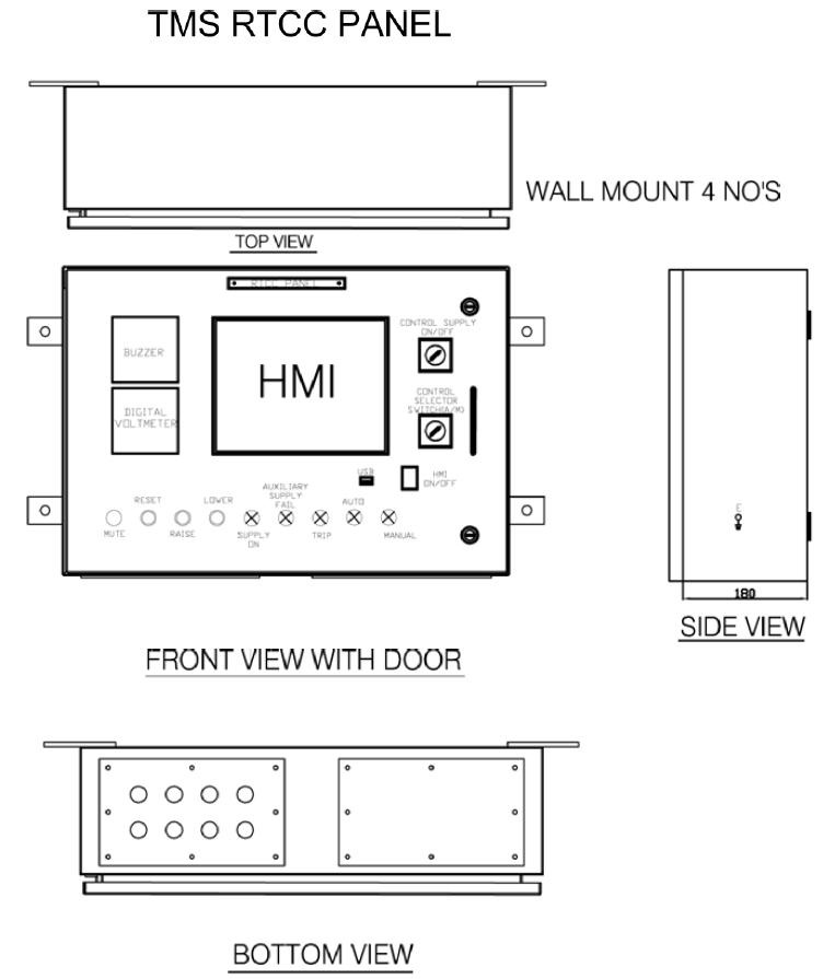
HMI 10.1 TFT Touchscreen
Operation Types Local, Remote
Tap Position Resistance Input / mA / Binary Coded
Cooler Function
  • OTI/WTI Analog Instrument
  • Automatic cooler based on Temperature set points.
  • Fan Exerciser based on user selection.
  • Operating status of FAN’S.
  • Running Hours of FAN’S & PUMP’S.
Regulation Mode
  • Auto, Manual
  • Line Drop compensation (optional feature)
Transformer Data
  • Transformer Loss of life Transformer Overload Capability
  • Cumulative Hours spent at each TAP position.
  • Cumulative TAP counts for each TAP position.
  • Cumulative KVA for each TAP position.
  • Cumulative Kilowatt-hour delivered at each TAP position.
  • OLTC Motor current trends
Options for Parallel Operated transformers Independent / Master / Follower / OFF mode
LOGs
  • Alarm and event logging
  • Temperature OTI/WTI/Oil Level/HOTSPOT/Ambient and IED’s
  • Data export to text and Microsoft Excel.
IEDs (optional as required) Fiber optic direct hot spot temp measurement, Dissolved Gas Analyzer, Bushing Monitor, Smart Breather, Others on Request
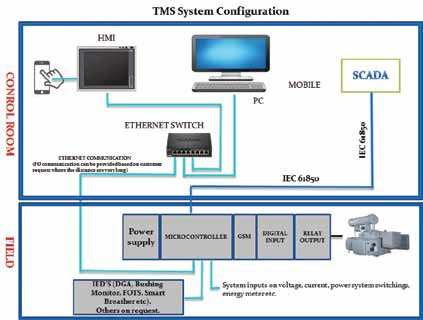
Mobile Mobile Access through VNC/GSM
Digital Inputs Electrically isolated input, Signal voltage 50-250V AC.
Digital Outputs Electrically isolated relay contacts.
Analog Inputs Current / voltage/ Resistance
Power Supply 88 – 264VAC / 125V – 373VDC / 47 – 63 Hz
Operating Temperature 0°C to 60°C (Others on request)
Storage Temperature -40°C to +85°C
Interface
  • 1 x RJ45 (Ethernet MODBUS TCP/IP)
  • 1 x RJ45 (IEC61850 – Copper / FO)
  • 1 x RS485 (MODBUS RTU for IED)
Housing Din Rail Mounting
EMI/EMC compliances
  • IEC 61000-4-2, IEC 61000-4-4,
  • IEC 61000-4-5, IEC 61000-4-8,
  • IEC 61000-4-9, IEC 61000-4-11,
  • Others on Request
Dimensions
Image Not Found!
Image Not Found!
Gallery
Image Not Found!
Documentation

There is no firmware available for this product.

Having questions? Send us an inquiry!